How to Read a Subsurface Utility Map and the Insights Provided
How to Read a Subsurface Utility Map and the Insights Provided
When planning construction or infrastructure projects, the hidden world beneath our streets can be as important as what lies above. For engineers, surveyors, and construction professionals, understanding this hidden network of utilities and infrastructure is critical. A single misinterpreted line or missing data point can lead to costly project delays, safety hazards, and damage to vital assets. Utility errors and omissions can quickly derail both large and small projects, as seen in infamous projects such as Boston’s Big Dig, California’s I-405 project, and the Walnut Creek tragedy in 2004.
Subsurface utility maps are essential tools that enable us to visualize and navigate this underground complexity, offering insights into where utilities run and how deep they’re buried. Yet reading these maps effectively requires more than just technical skill; it demands an understanding of how they were created, what data they’re built on, and how the standards behind them have evolved. Moreover, it’s essential to determine how reliable and complete the drawings are, and if all the data is contained in a single source document.
Historically, Subsurface Utility Mapping (SUM) was as much an art as a science, with hand-drawn plans created through careful survey work and meticulous detail. Today, advanced Geographic Information Systems (GIS), Computer-Aided Design (CAD), and Building Information Modeling (BIM) technologies have replaced the drafting table, transforming data points into powerful databases, creating clear and concise CAD plans, and generating digital visualizations. To comprehensively read a subsurface utility map and extract meaningful information, professionals must interpret both the visual language and the confidence level of the underlying data.
History of Underground Utility Mapping
In metropolitan areas, underground facility construction dates back to the 1800s when water, wastewater, and gas lines were first placed below the surface. As electrical and telephone networks expanded around the turn of the century, overhead lines were increasingly relocated underground, creating a dense and complex subterranean infrastructure in many cities. These utility networks represented an infrastructure renaissance that improved the lives of residents and businesses in urban areas, enhanced health and sanitation, mitigated epidemics, improved public safety, and facilitated the growth and expansion of communities.
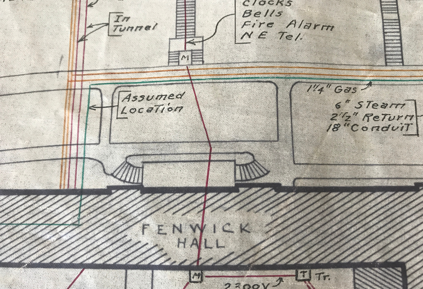
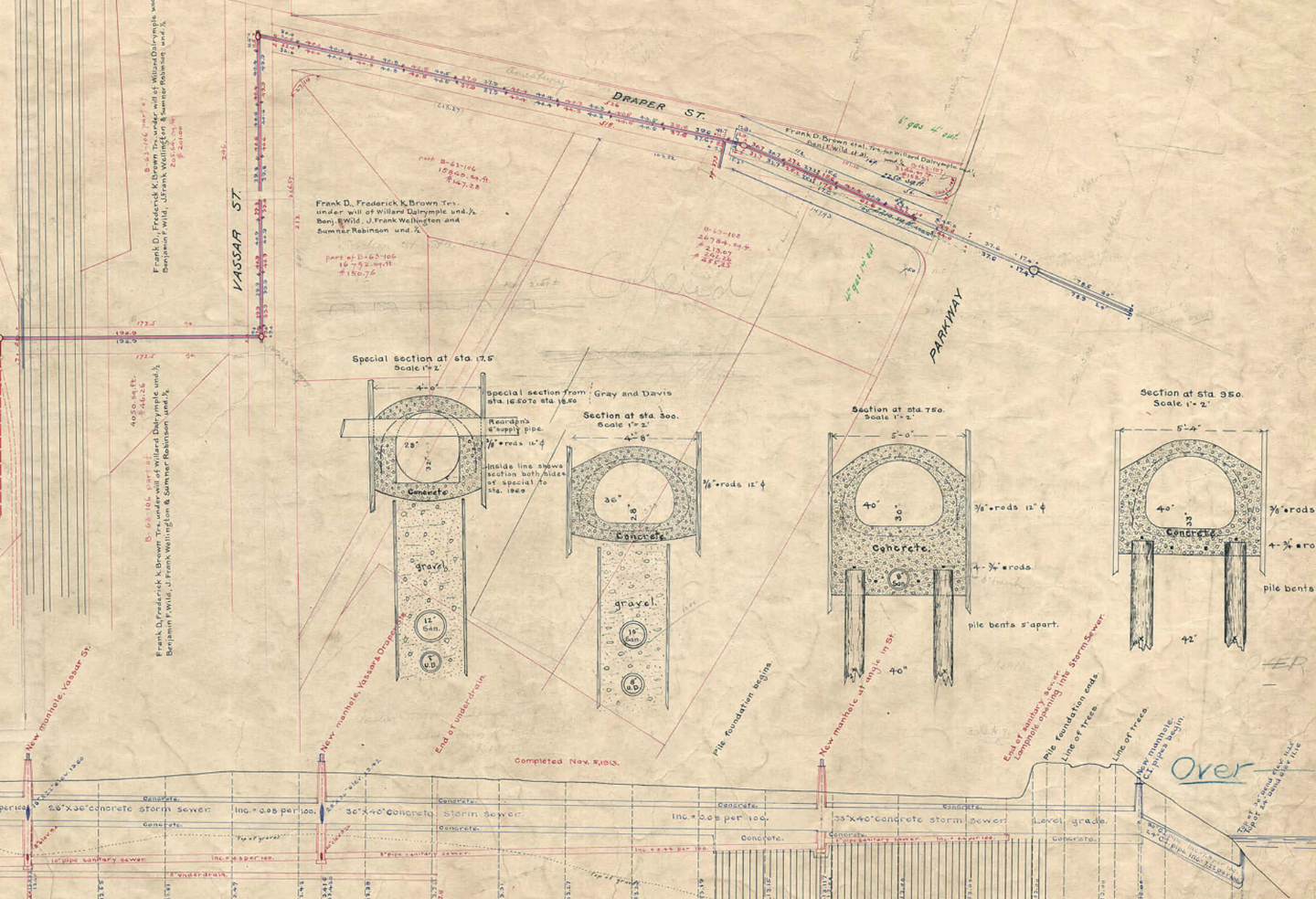
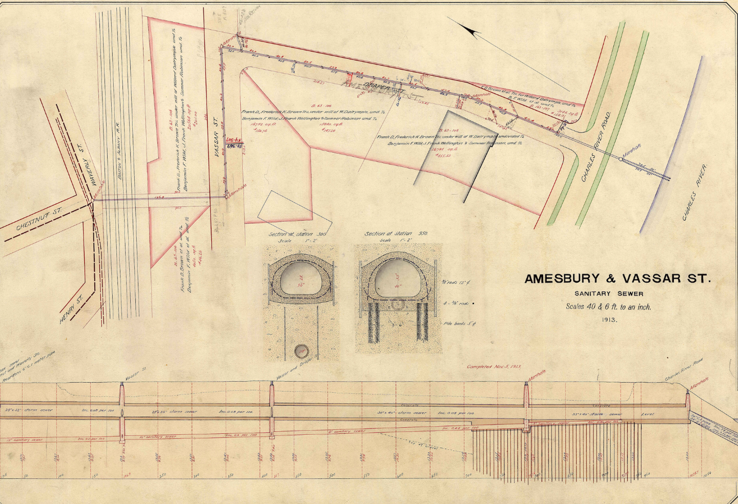
Early utility maps were meticulously prepared by surveyors and engineers who understood the long-term value of high-quality records. These plans were often drawn to scale, color-coded, and annotated with pipe sizes, materials, depths, and installation dates. It was not uncommon to find utility plans with the geometric information that helps today’s utility surveyors recreate the path of networks. Some organizations, such as the Edison Companies, even had dedicated survey crews who not only mapped their own networks but also recorded nearby utilities for reference.
These historic records were based on field surveys, making many of them remarkably reliable even today. In some areas, these legacy maps remain the most reliable source of information for older neighborhoods. Through the acquisitions of other surveying companies, DGT has maintained archives of these early plats, preserving details that are often lost in modern data conversions.
While not every asset owner was as diligent—many older records have been discarded or degraded—these early efforts laid the groundwork for today’s mapping practices. They also remind us that the clarity, accuracy, and annotation standards of the past continue to influence how we record and interpret underground utilities today.
From Paper to Digital: How Utility Mapping Has Evolved
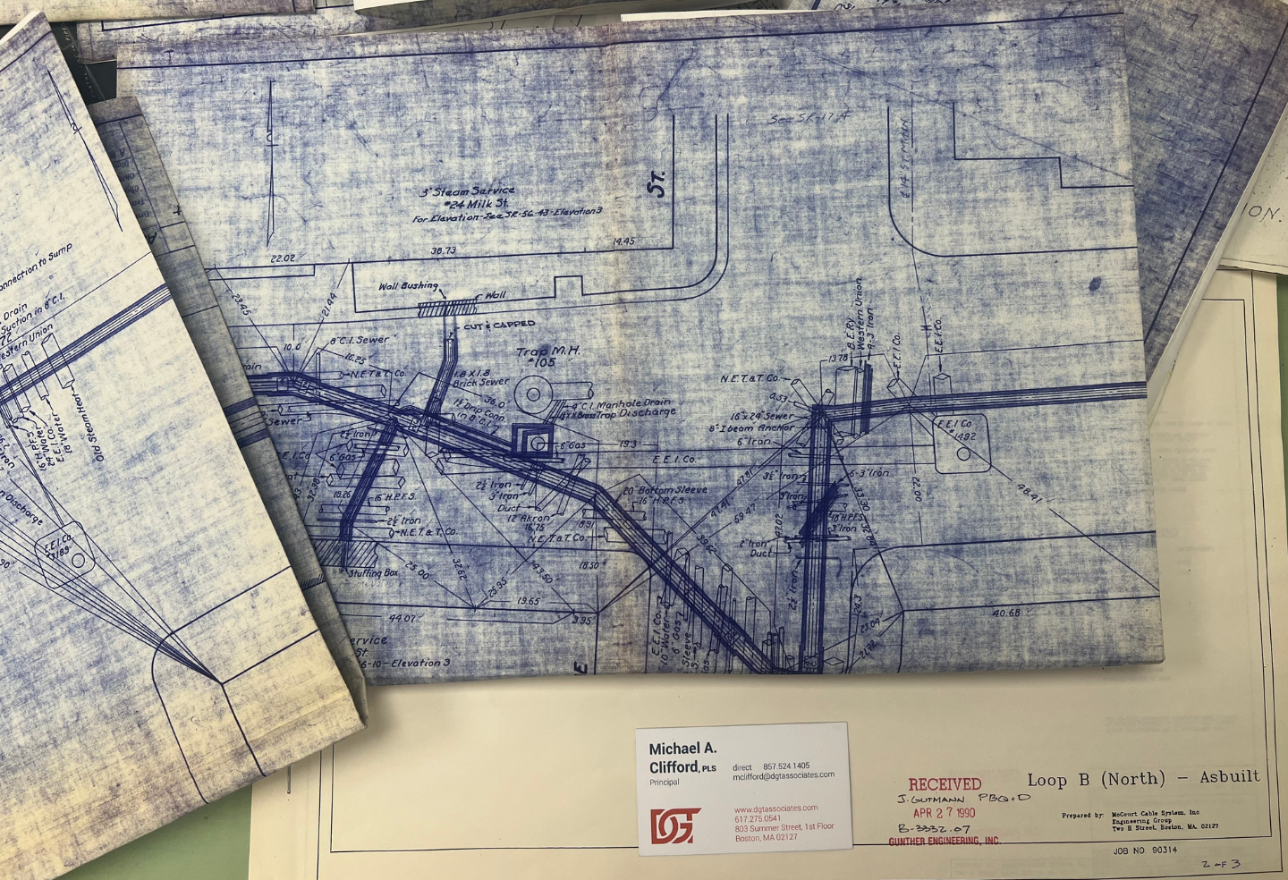
Today, utility mapping has largely transitioned from hand-drawn plans to sophisticated digital platforms that store, analyze, and share data in real time. The move from ink and vellum to databases and sensors has transformed not only how utilities are recorded, but also how they are managed throughout their lifecycle. A quarter of a century ago, many asset owners digitized the old paper plans and converted utility data to digital files. Many of these digital recreations were a good start, but not all pertinent information has leaped into the digital world.
Geographic Information Systems (GIS) now form the foundation of most utility asset management programs. These systems enable owners to build georeferenced databases that store attributes such as utility type, size, material, and installation date, along with links to images, videos, inspection reports, as-built documents, and maintenance records. GIS platforms are powerful for operations and maintenance teams, including plans, accounting, and inventory records, but are often less practical for engineers and surveyors in the field. Many maps use simple, single-line symbology for both large and small utilities, with nodes representing complex structures. When exported as static PDFs or JPEGs, much of the underlying data’s value is lost for design or construction purposes. Despite many asset owners having mature GIS databases, today, land surveyors who request utility data for underground networks receive simplistic PDF files with little or no locational data. As a result, despite modern GIS capabilities, SUM practices often feel effectively stuck in the 1980s.
Computer-Aided Design (CAD) Systems remain the workhorse of the AEC industry, providing the workflows that engineers and designers rely on for project planning, infrastructure modification, and new construction. CAD excels at precision, allowing teams to work in 2D or 3D and overlay topographic surveys, site features, and utility locates. In summary, CAD provides a flexible environment for compiling and visualizing utilities from various sources, including GIS exports, legacy data, and comprehensive field investigations, into comprehensive base maps.
Building Information Modeling (BIM) represents a further evolution. By integrating CAD design, GIS data, and project workflows, BIM creates a digital model of the built environment, encompassing both above-ground and underground elements. This approach supports real-time updates, facilitates faster design changes, and enhances the visualization of spatial conflicts between utilities and new structures. While BIM is the accepted term used by design and construction firms, DGT coined the phrase Subsurface Information Modeling many years ago better to reflect the 3D mapping of the underground built environment.
Despite these advances, challenges persist. Not all GIS and CAD systems communicate seamlessly, and data quality often depends on the accuracy of the original records. Many owners still rely on legacy maps or incomplete archives, so even digital data can lack proper attribution or standard-of-care documentation. Therefore, interpreting modern subsurface utility maps still requires professional judgment—understanding both the strengths and limits of the data behind the digital lines. Moreover, engineers and surveyors tend to rely on the survey of 811 mark-outs. While this process is a good integration of asset owners locating information from paint and flags to digital data, all too often, a bona fide subsurface utility investigation by a professional utility surveyor is overlooked or dismissed.
Translating Map Symbols and Data Reliability
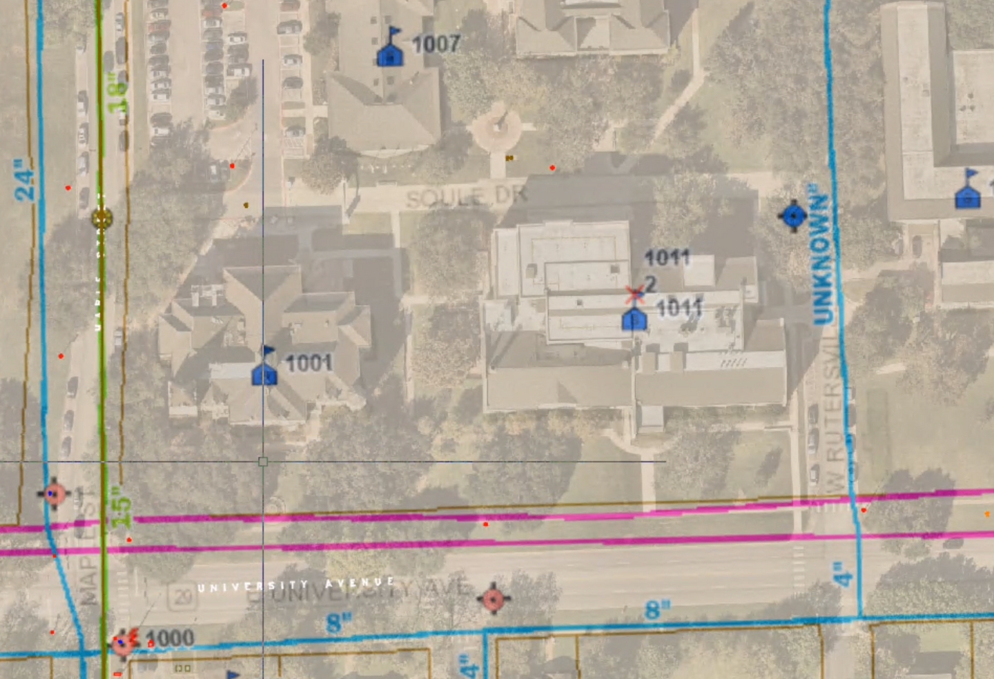
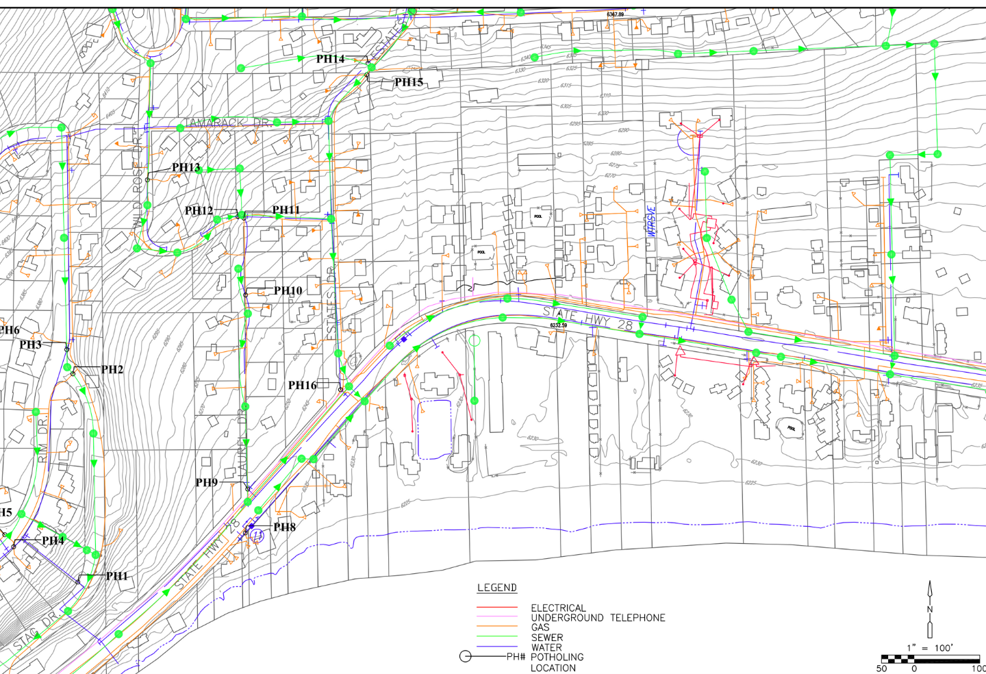
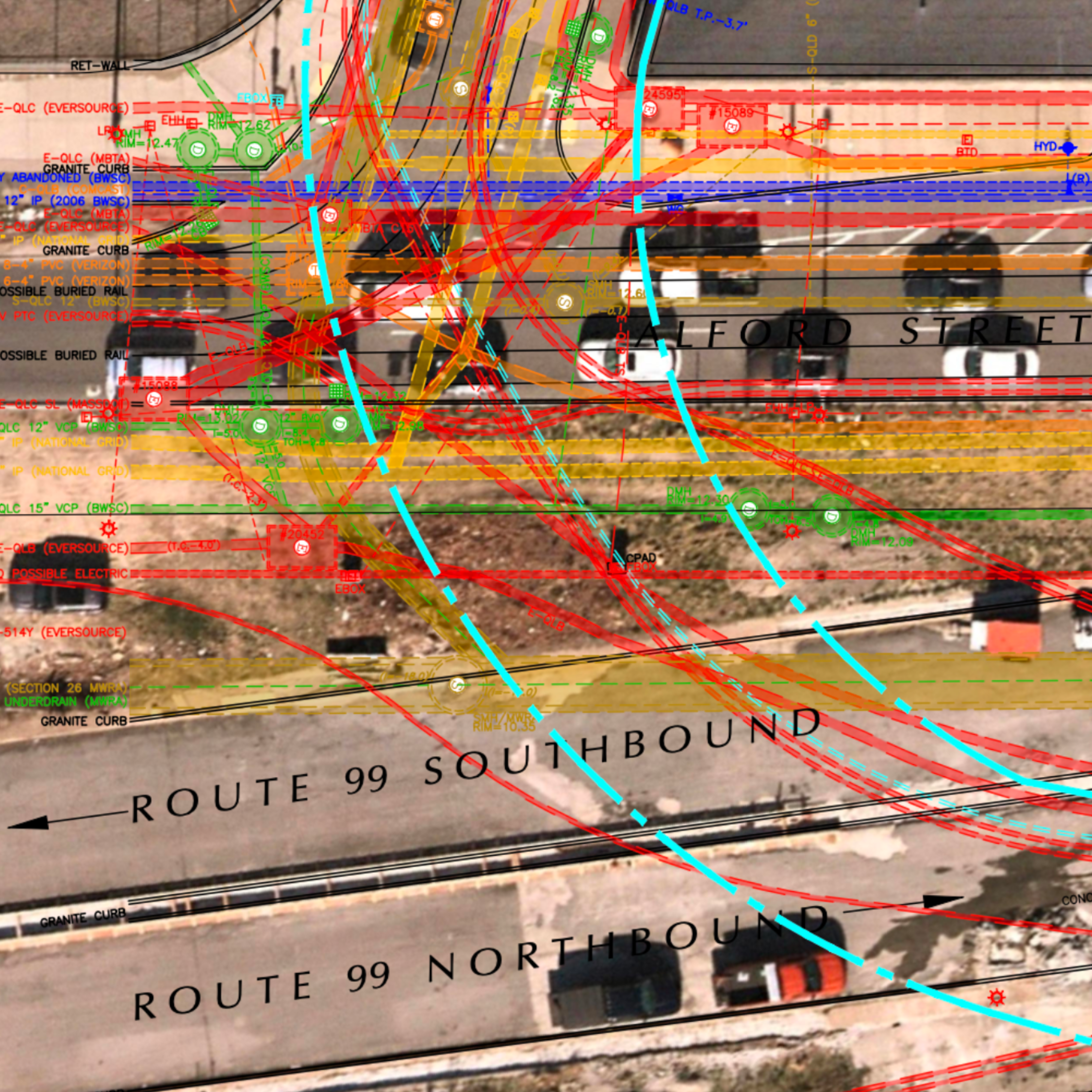
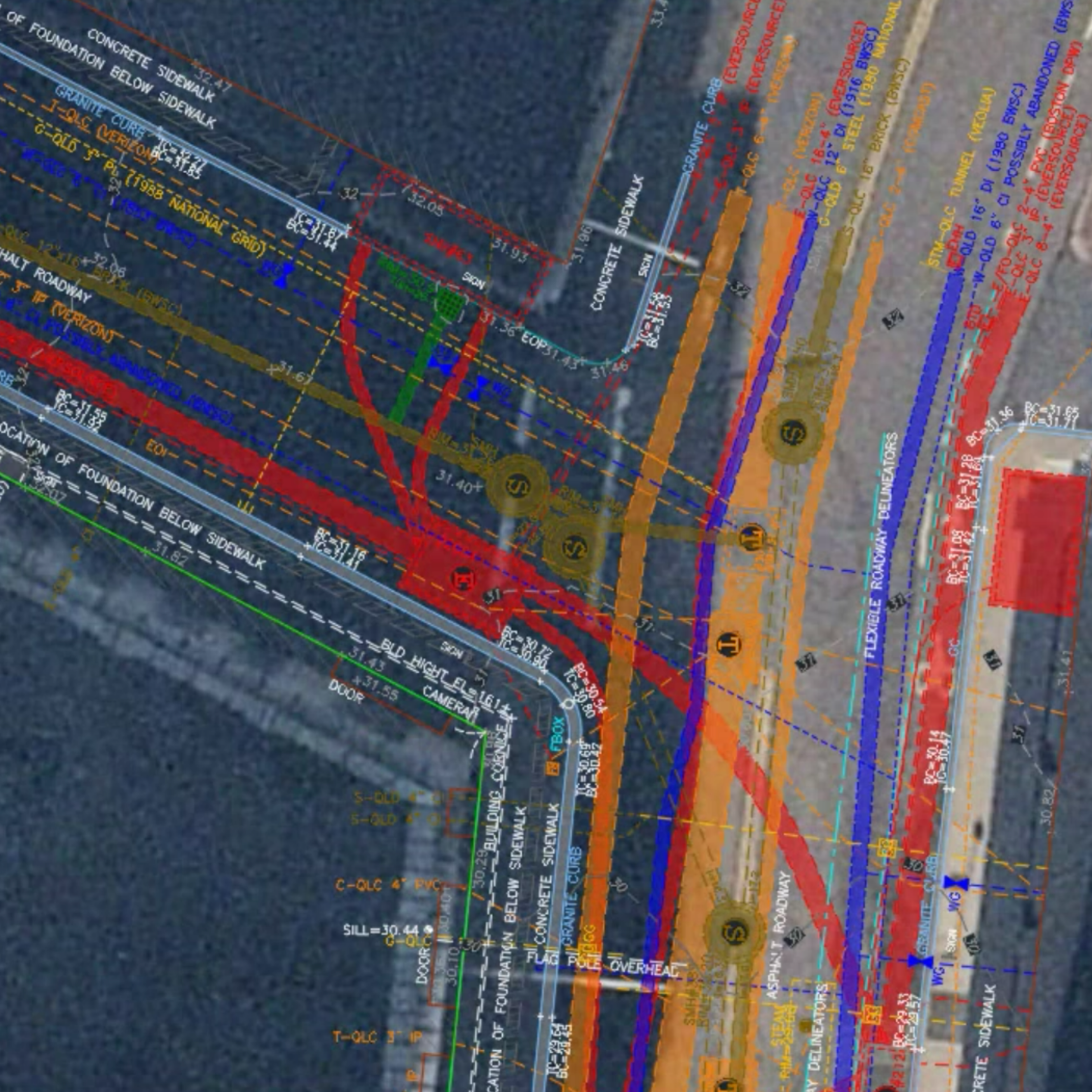
Subsurface utility maps use standardized symbols and color codes, often following the American Public Works Association (APWA) standards: blue for water, yellow for gas, red for electric, orange for telecommunications, green for sewer and drain lines, purple for reclaimed water, and pink or white for survey markings. These color codes are consistent across the U.S. and serve as the universal language of underground mapping and underground damage prevention programs.
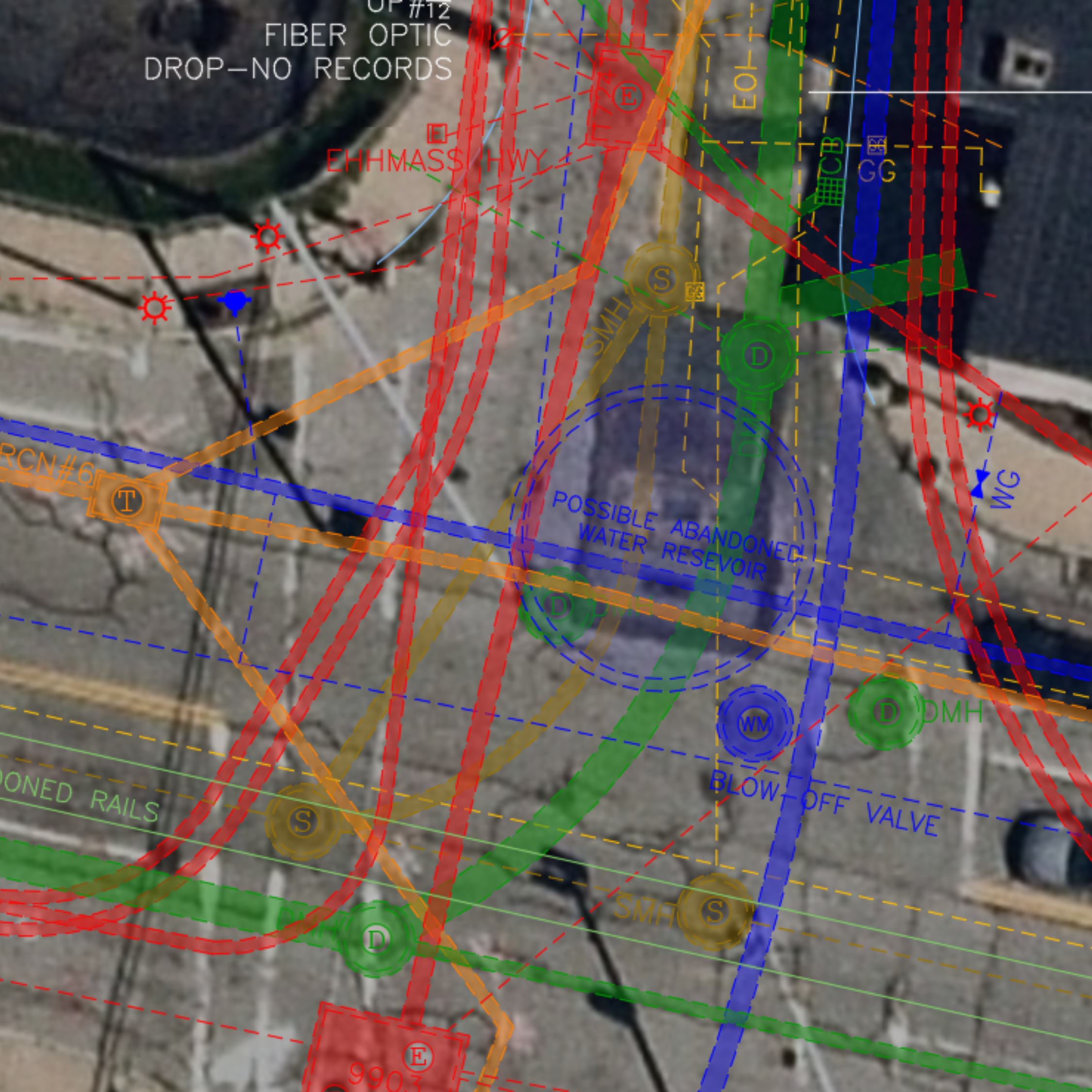
On the map, lines represent utility routes, which may appear solid, dashed, or dotted depending on the type and confidence level. Nodes mark structures such as valves, manholes, handholes, and junction boxes. Annotations often indicate pipe size, material, depth, owner, and installation date. However, understanding the reliability of utility maps is just as important as interpreting the symbols. The ASCE 38-22 (and its predecessor 38-02) standard defines Quality Levels for subsurface utility data:
- QL-D: Compiled from existing records with no field verification.
- QL-C: Based on site observations of surface appurtenances.
- QL-B: Data collected using remote sensing technologies.
- QL-A: Verified by physical exposure, such as excavation.
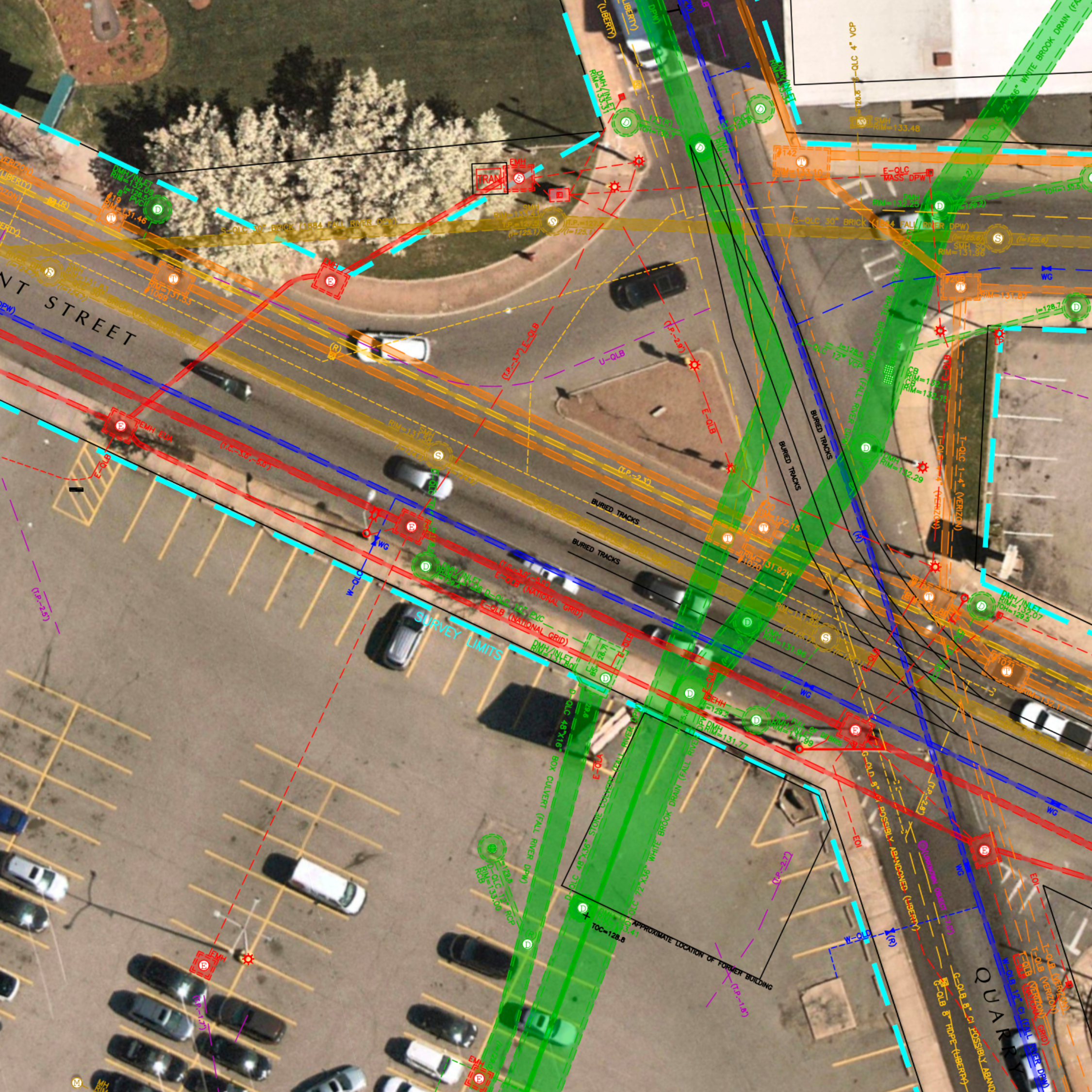
Modern utility maps often combine these different utility quality levels in a single drawing, each color-coded or labeled with its respective QL designation. Knowing which parts of the map are verified versus inferred allows engineers to assess risk and decide where further investigation is warranted. When a map does not specify its quality level or lacks supporting metadata, it should be treated with caution, especially in congested corridors or high-stakes projects. A clear understanding of these standards helps professionals separate assumptions from verified facts and transforms a static drawing into a reliable decision-making tool for design, excavation, and safety planning. After all, without exact utility information in a single source document, no project team can make informed decisions for risk assessments and the protection of underground networks, the public, and construction teams.
Practical Steps to Read a Subsurface Utility Map
Reading a subsurface utility map can feel overwhelming at first, especially when faced with a tangle of lines, symbols, and annotations. However, by approaching the map systematically, you can extract accurate and actionable information. The key is to understand the source, assess reliability, interpret the symbols correctly, and plan for verification where necessary. While you’ll still need a professional to verify and appropriately apply map insights, following these steps can help you more confidently use the map to guide design, construction, or maintenance decisions. By following these steps, professionals can confidently interpret subsurface utility maps and make informed decisions.
- Identify the data source – Determine whether the map comes from historical records, GIS, or CAD.
- Check for reliability annotations – Look for ASCE 38-22 quality levels, survey dates, and utility owner information.
- Interpret symbols and color codes – Lines, nodes, labels, and depth annotations each convey different pieces of information. Pay attention to line styles (solid, dashed, dotted), node symbols (valves, junctions, manholes), and any accompanying annotations, as they convey critical engineering details.
- Cross-reference information – Compare old maps, as-builts, and visible surface appurtenances to fill gaps.
- Plan for verification – When critical infrastructure is involved, pursue QL-B (like electromagnetic induction or ground-penetrating radar) or QL-A verification (like test pits) to confirm exact locations.
- Read the notes – Project notes contain vital information. While this is often considered the “fine print,” it is crucial to understand the plan details, including insights into the plan preparation, such as project survey datums.
- 811 Integration – Most cavy design and construction teams understand that every project requires a valid 811 ticket request prior to breaking ground. Comparing the SUM plan prepared by the design engineers’ team with the 811 mark-outs will help ensure all the utility information is accurate, current, and complete.
Insights Provided by Subsurface Utility Maps
In the complex world beneath our feet, a subsurface utility map is only as useful as the expertise applied to interpret it. Modern utility maps contain more than a collection of colored lines, it’s the product of historical context, technical skill, and thoughtful evaluation of data accuracy. By combining old records, advanced digital tools, and ASCE 38-22 quality annotations, professionals can make informed decisions, avoid costly mistakes, and design projects safely and efficiently.
At DGT Associates, we have decades of experience helping project teams navigate the complexities of underground infrastructure. By combining historical maps and records with modern GIS and CAD data, along with advanced SUM techniques, we provide accurate, actionable insights that support informed decision-making. Whether integrating older records with new survey data or applying ASCE quality standards, our approach ensures that utility maps are not just documents—but practical tools for reducing risk and guiding projects successfully.
Learn more about our SUM services.