One Post Office Square: An Unconventional Façade Laser Scan
One Post Office Square: An Unconventional Façade Laser Scan
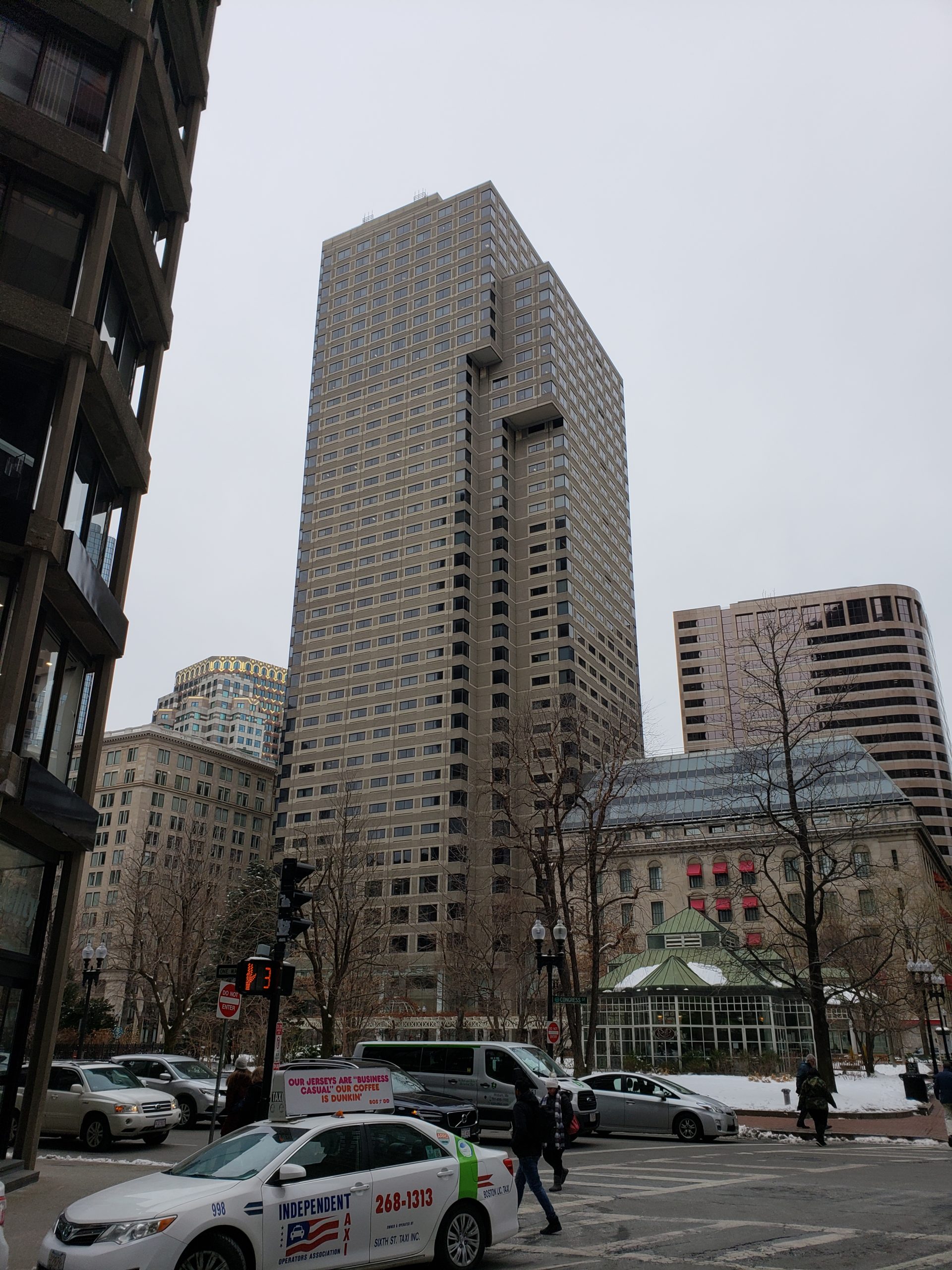
Centered in the heart of the Financial District, Post Office Square has been a designated Boston landmark since the 18th century. Made up of a public park, shops, offices, and restaurants, Post Office Square is a quintessential area that has seen many different faces since its establishment. Over the course of many years, DGT and our legacy firms have been involved with various projects centered in Post Office Square. The most recent is the iconic One Post Office Square (OPOS) building.
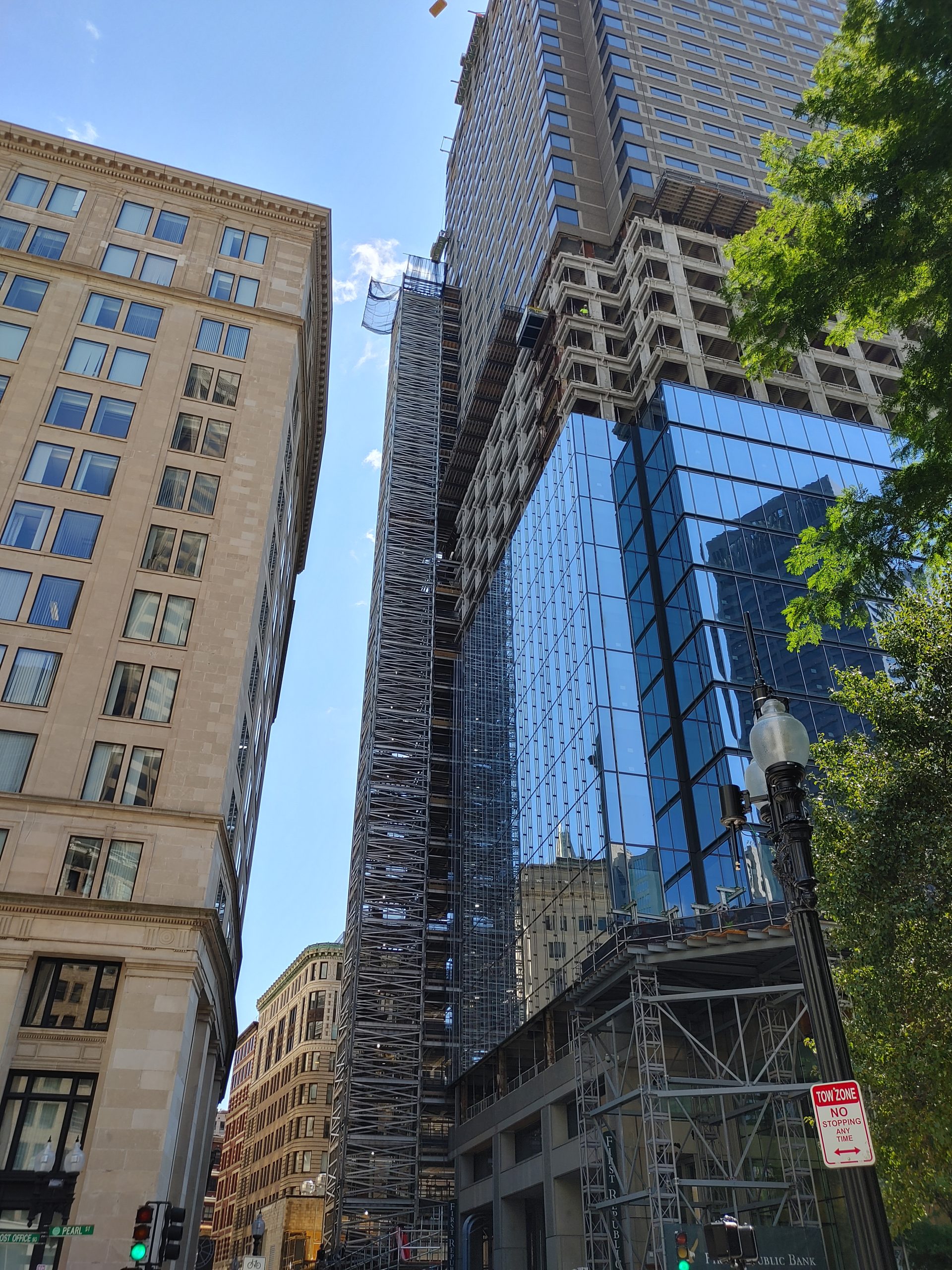
To aid in the building’s modern renovation, DGT was hired by local contractors to perform a 3D laser scanning façade survey to replace the existing concrete façade on the 42-story high-rise building. Most projects like this are straightforward in that our team can establish our grid and control points, and record structural details from top to bottom, inside and out. But, OPOS had a unique situation—existing tenants reside between floors 20 and 37, and those floors are off-limits and inaccessible to crew. While this is an unconventional challenge, it’s one that DGT has taken on with confidence to produce a reliable, high-quality 3D documentation of the façade.
Typically, for a project like this, we would establish our grid on the first floor and by using a vertical plumb line, we bring control straight up to the top floor.
3D Façade Mapping
The survey work, nearing completion after over a year of work, consisted of three key phases:
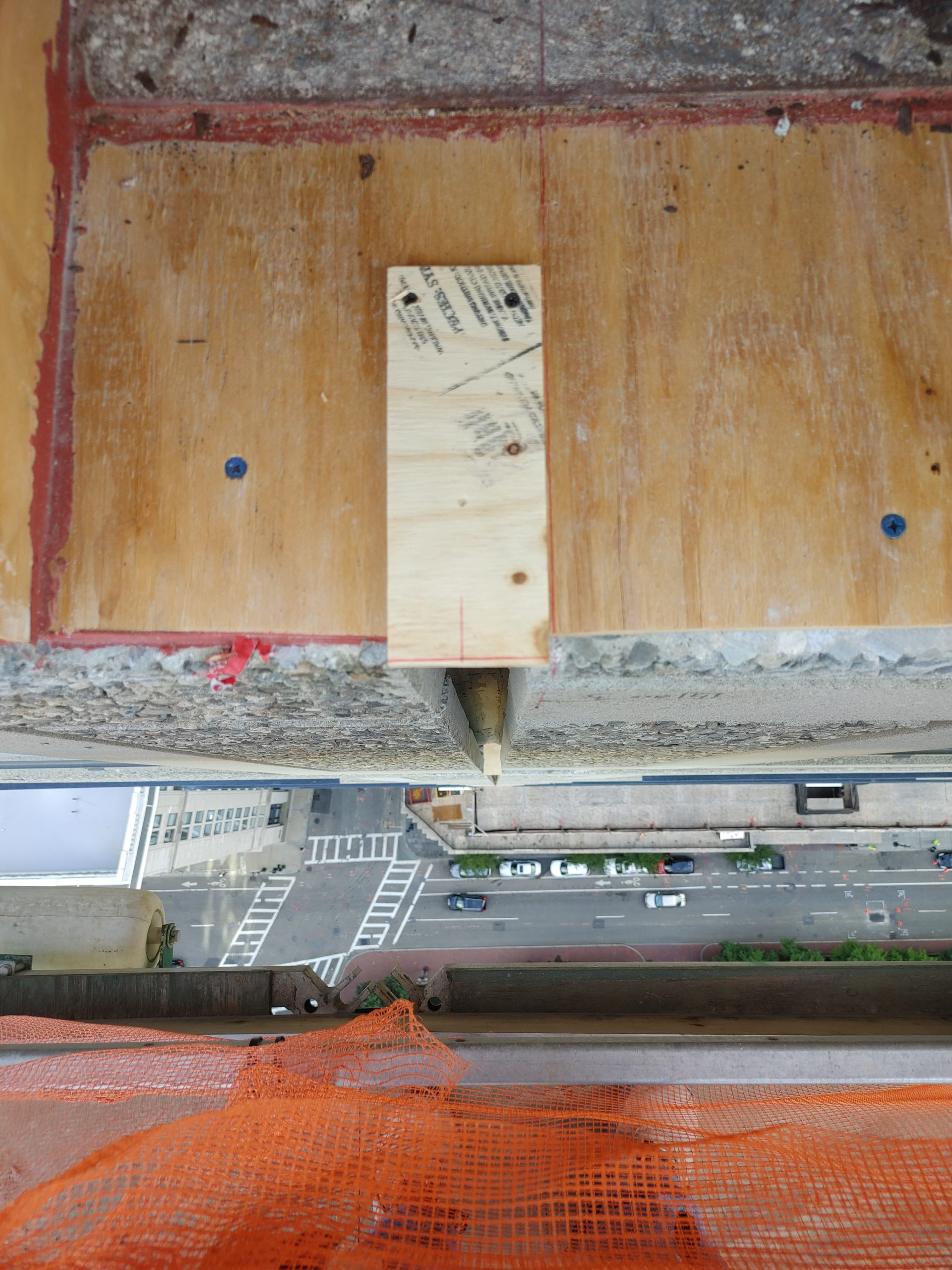
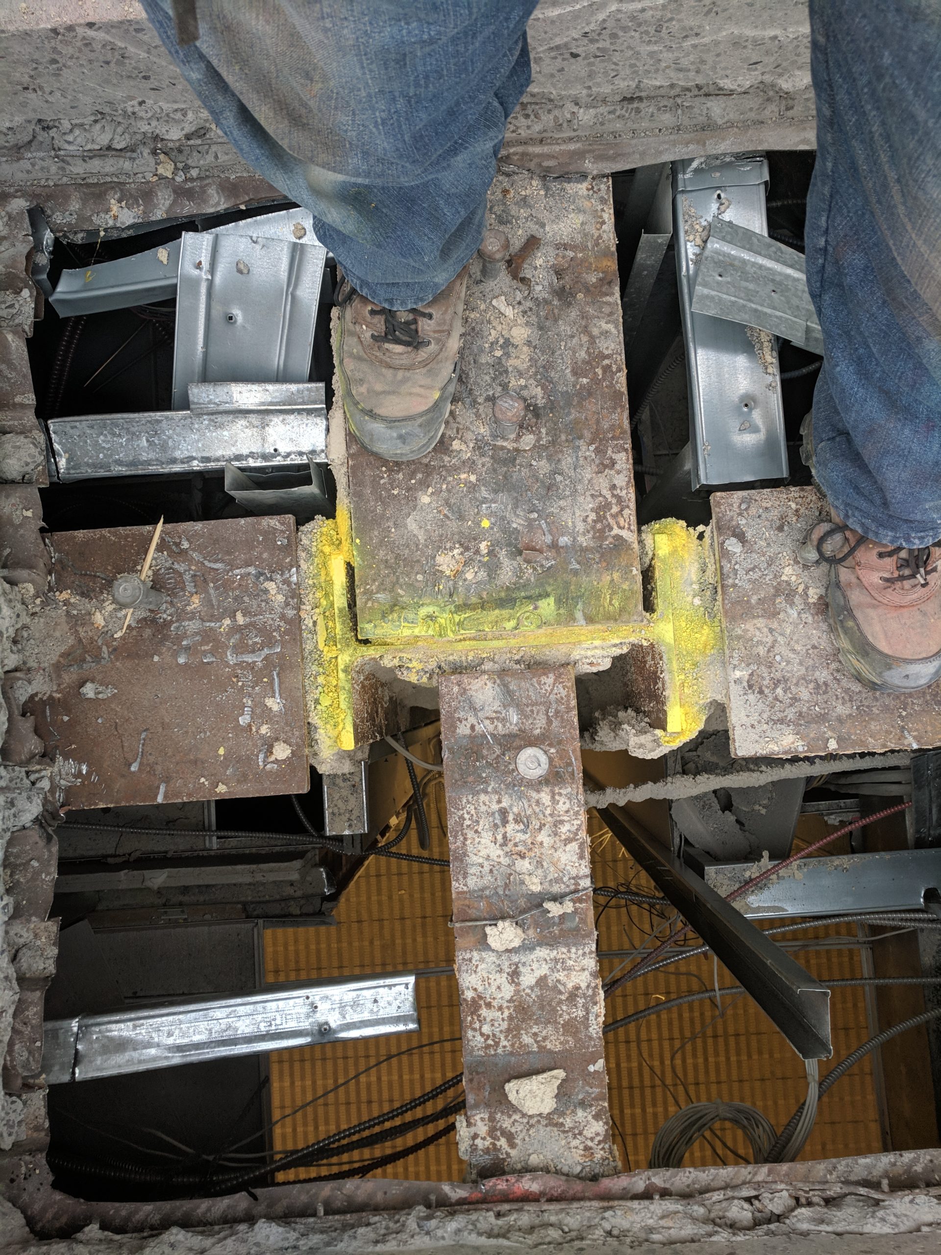
- Phase 1: To start, we established control around the adjacent street blocks and neighboring buildings. Next, because the seventh floor was the only floor with exposed steel, we removed windows on the seventh floor and shot in traverse from street. We started there to establish a building grid holding a best-fit solution based off the steel. This information is critical because it gets carried throughout the whole building. With the building grid established, we began measuring from the seventh floor up to 19th and again from the seventh down to the first floor.
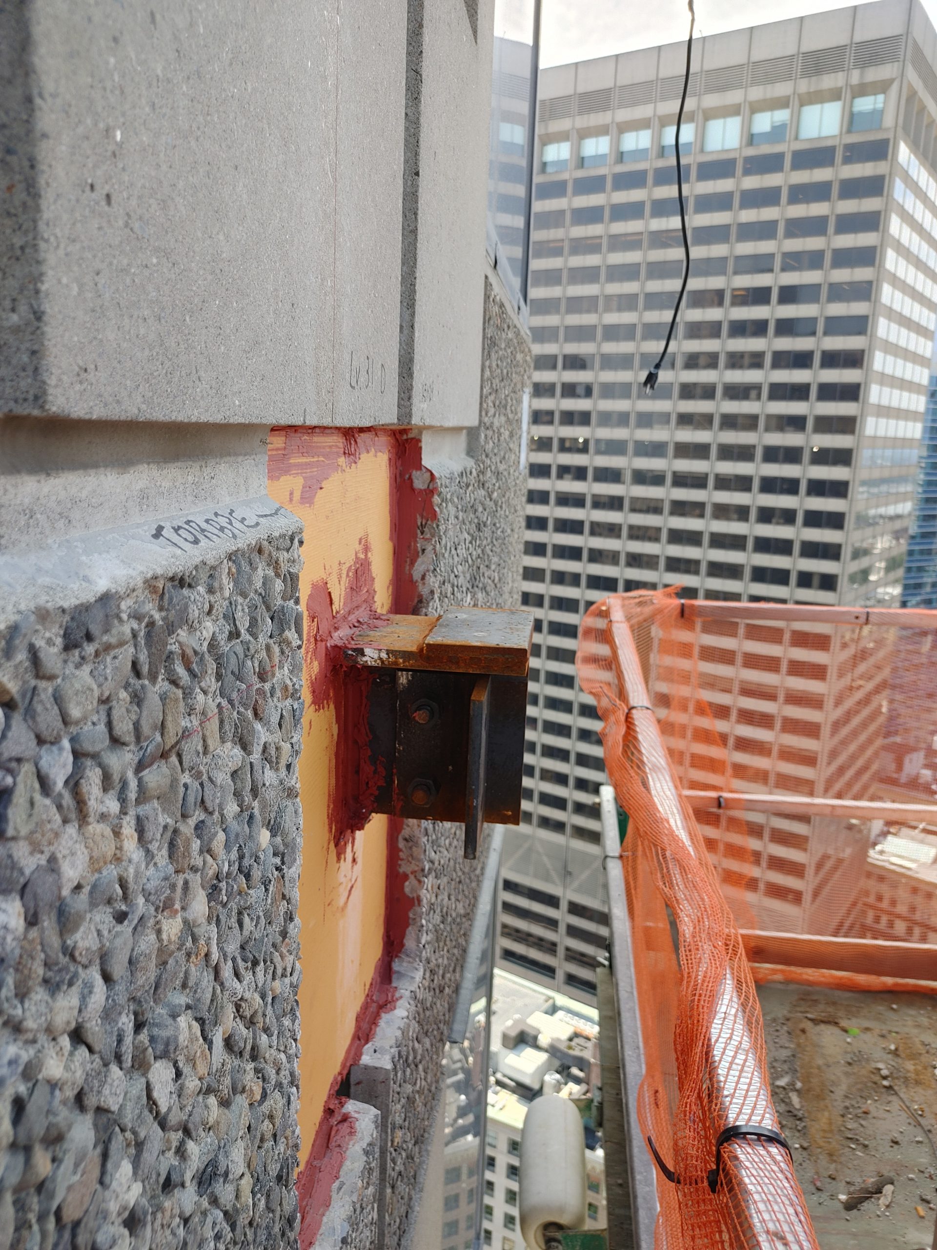
- Phase 2: With an established building grid, we monitored and measured the existing precast from floor 21 to 42.
- Phase 3: This phase required creativity given that residents are occupying 17 of the 42 floors. To assist, we hired a company to scale down from the top of the building, 42 floors up, and set large targets over the building façade on the levels we did not have access to. Using the targets, we surveyed from the street level to determine where the façade was relative to the established building grid. We also had to use the roofs of adjacent high-rise buildings and remove windows to gain accurate measurements. While these methods are nontraditional, they were the best way to capture all the information needed to design a new façade that is consistent throughout.
Though the project is ongoing, our work has already proved to be valuable to the many stakeholders involved. After our measurements in our first few phases were complete, we shared our findings with an architect on the project, who had based a Revit model off of existing records. After receiving our measurements, the architect discovered their design was off by about two to three inches and had to redo the Revit model. While using as-builts is a common practice to save time, this project would have been extremely costly to make the needed adjustments in the field had the error not be caught with our survey.
Underground Mapping & Preservation
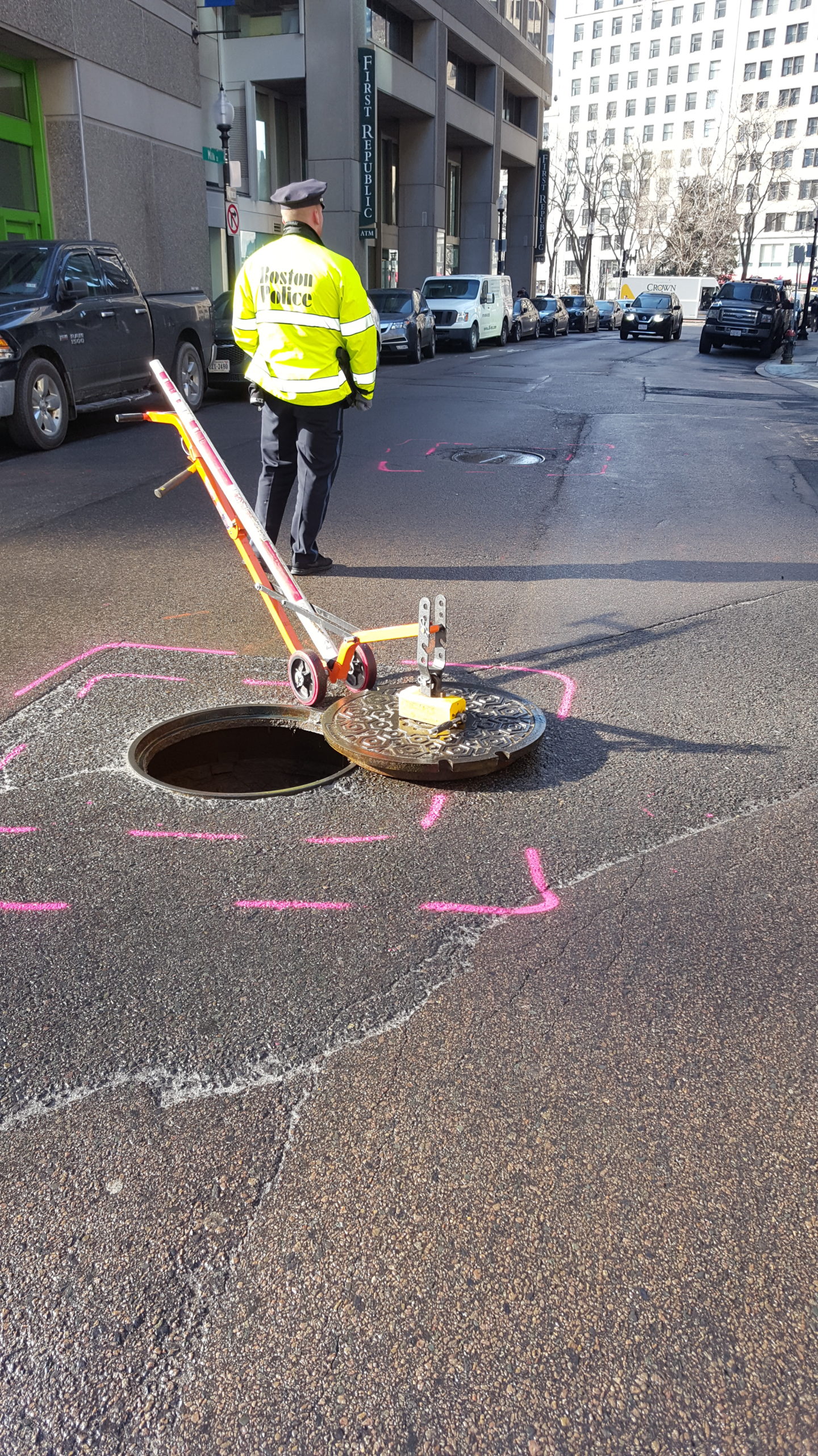
With the aboveground measurements complete, we’re continuing our focus to belowground. Running concurrently to the aboveground façade mapping, our subsurface utility mapping team has been on-site to map the underground facilities below and around OPOS to aid in further construction.
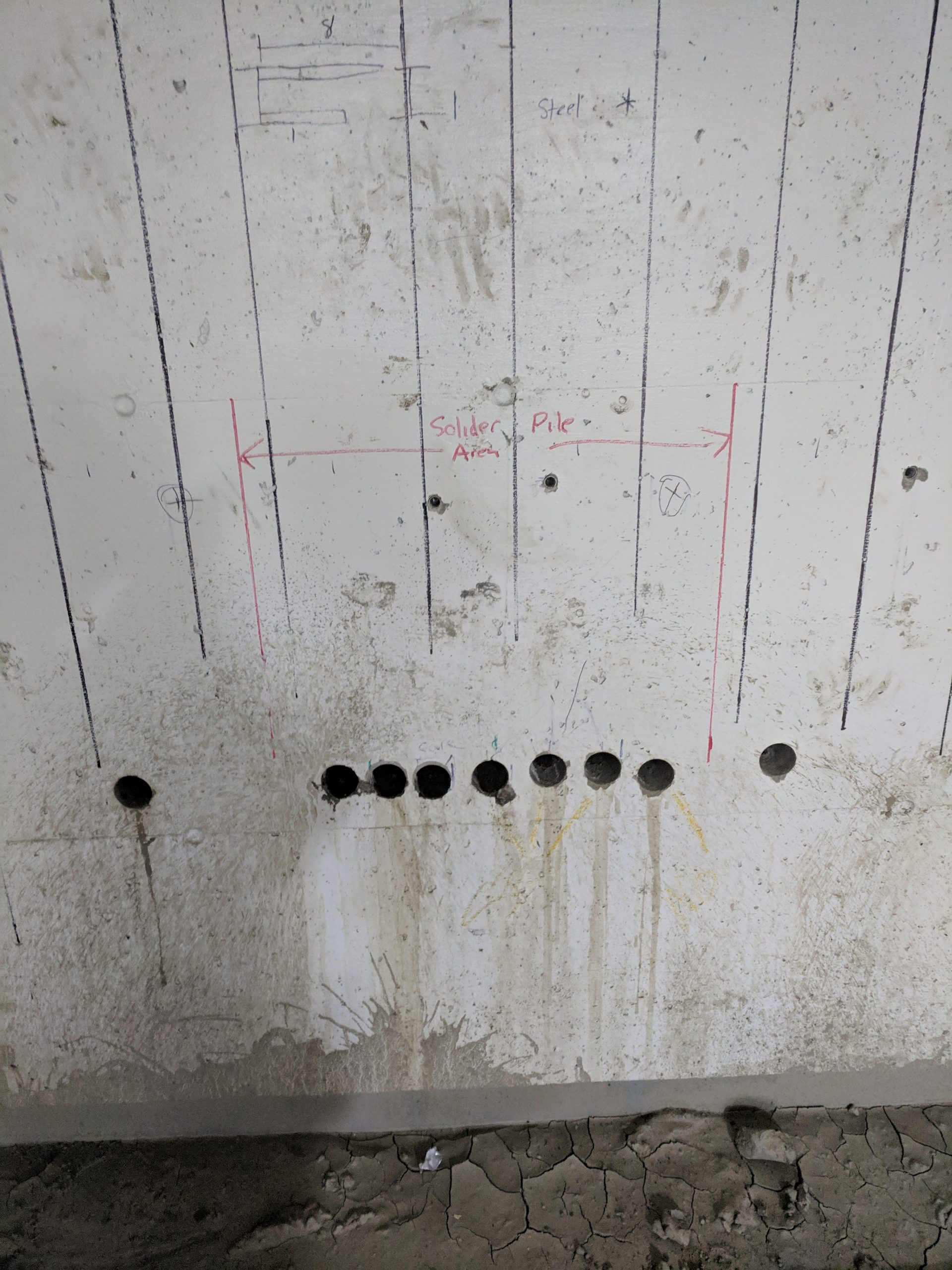
Although the building is being renovated, the existing foundation is staying. So, in order to support the foundation through renovation, the contractor will need to perform auger drilling to install piles to add support to the foundation. To help plan these piles, DGT has mapped the underground environment and the exact locations of existing underground utilities. We combined survey data from cored holes in the foundation and LiDAR underground mapping inside the utility chambers, and integrated all of the data into our 3D model to give the contractors a complete visualization of above- and belowground environments.
For this project, and all DGT projects, accuracy in our measurements is of the utmost importance. One mistake can greatly affect design plans. We were contracted for our commitment to uphold accuracy despite project challenges, and as always, we’ve balanced respecting traditional methods, while also being able to think out of the box to generate new solutions.


